
Education City Tram Stops
Doha, Qatar
Practice Grimshaw
Role Project Architect
Duties
Management of design delivery to client
Oversee team in development of construction documents
Coordination of design-assist with contractor
Project Description
The Qatar Foundation commissioned the Siemens Tram Consortium, to design and build a new tram system that operates without overhead contact lines in Education City, the university center in Doha, Qatar. Grimshaw was engaged by the consortium to design a series of seventeen at-grade open air stops for the system which were all developed as variations of a single architectural and structural design.
The minimalist design integrates the structure and enclosure in a way that makes them one and the same. A cable-net structure is held aloft by elliptical columns, spanning the tram tracks and sheltering waiting booths and station furniture below. Building services were carefully integrated with the structure in order to support the tram’s operation.
The structure also supports components for the tram’s unique propulsion system, a hybrid energy storage solution that utilizes batteries that recharge via an overhead charging rail at each stop. This system eliminates the need for expensive and obtrusive overhead catenary wiring. The charging rail acts as a sort of central nervous system of power and data, hovering between the canopy and platform.
Each station structure was prefabricated in order to allow for flexibility in production and construction while maintaining a recognizable line-wide character. The stops are located along 11.5km of track served by 17 trams each with a capacity of 233 people.
The completed system aims to allow for easy transit of the Education City campus, providing key infrastructure that integrates the tram with other forms of access including walking, driving and cycling.

A series of shelters with enclosed waiting rooms for an innovative wireless tram system
SITE
The People Mover System connects several locations between the North and South campus. The variety of site conditions lead to a solution that uses common elements applied to different site configurations.

Campus Site Plan

Stops Map
TRAM STOP DESIGN
Design Drivers
Ease of Circulation (Entering and exiting the stop , boarding and alighting the trams)
Structural Clarity (Legibility and expression)
Integral Design (Integration of architecture, structure, and systems)
Climate Responsiveness and User Comfort (Sun shading, photovoltaics, waiting rooms)
3 Stop Variations
Each of the tram stops are constructed using a “kit-of-parts” approach, where each of the stops is constructed from a combination of shop- fabricated, repeating components.

Repeated Identical elements:
Superstructure components: Inclined structural columns, glass clamps
Canopy glass panels
Column base covers that serve as benches on the platform
Exterior benches
Custom interior benches
Light fixtures
Custom lighting fixtures
Totems and other elements on the platform
Services spine for the incorporation of lighting etc.
Repeated elements with minor variation:
Glass canopies and their individual components
Superstructure: Columns and cable net assembly
Conditioned glass waiting rooms
Waiting platforms
Glazing assemblies
Tram Stop Parts

Canopy Geometry


General Arrangement

PLAN: ROOF
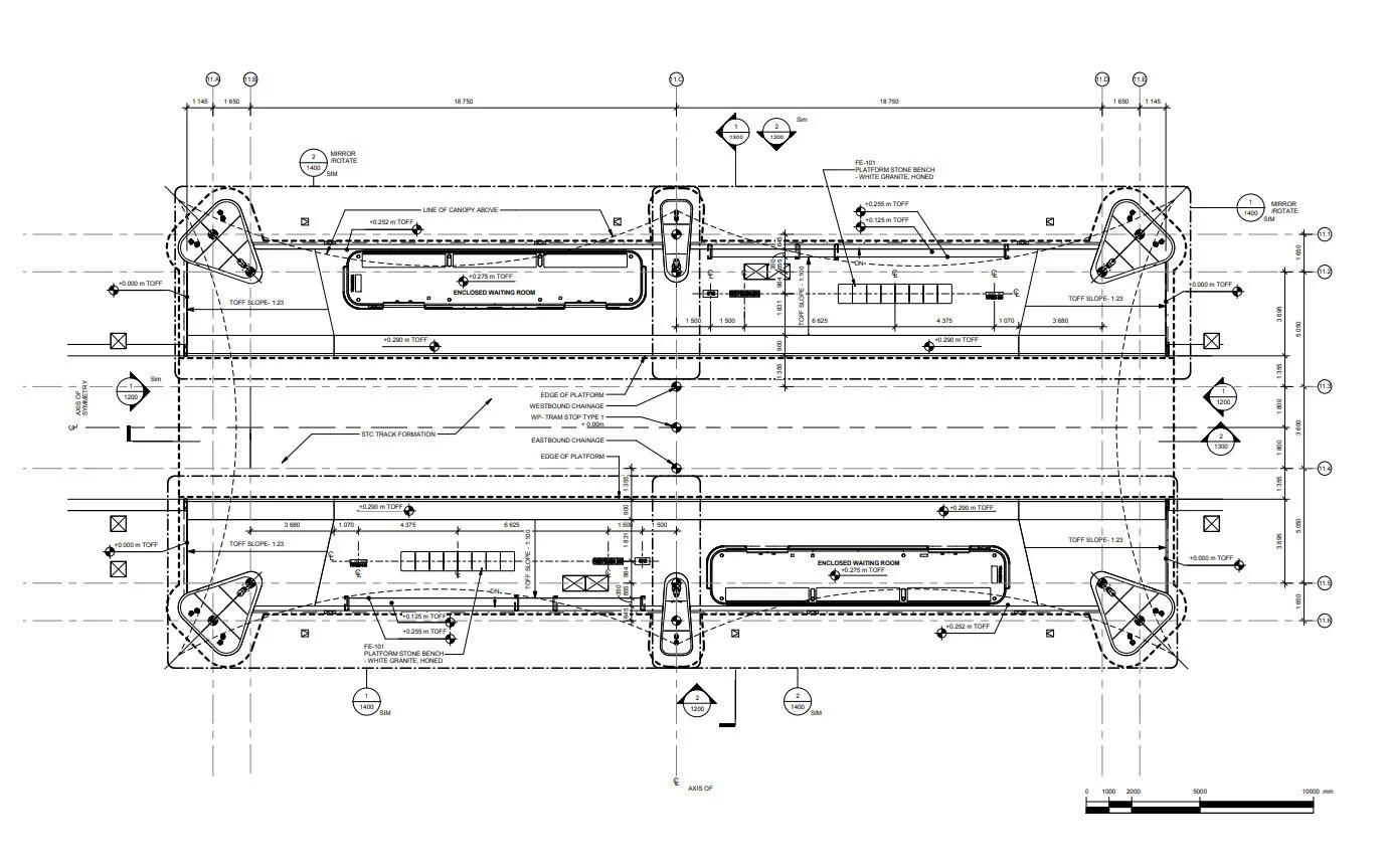
PLAN: PLATFORM

PLAN: ELECTRICAL SERVICE

ELEVATIONS
Details & Analysis

STRESS ANALYSIS

CANOPY GLASS MAKEUP


WAITING ROOM GLASS GEOMETRY & ANALYSIS

OCR FRAME SERVICES ROUTING

SERVICES INTEGRATION &
CONNECTION OF DEVICES TO OCR FRAME

SERVICES INTEGRATION THROUGH MAST

CANOPY PHOTOVOLTAIC SYSTEM WIRING DIAGRAM

PHOTOVOLTAIC WIRING DETAILS

GLASS CLAMP DETAIL
Lighting

LIGHTING LAYOUT

ILLUMINATION ANALYSIS MODEL
Graphics and Wayfinding

SIGN TYPES

WAITING ROOM GRAPHICS


